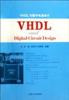
VHDL与数字电路设计
1970-1
江苏大学出版社
王俭,刘传洋,谷慧娟 著
193
随着半导体技术和专用集成电路(ASIC)设计技术的快速发展,可编程逻辑器件(PLD)技术日趋成熟、计算机辅助设计(CAD)技术和硬件描述语言(HDL)的日益完善,数字系统的设计可以直接面向用户的需求,根据系统的行为和功能要求,自上而下地完成电路在不同抽象层次下的描述、综合、优化、仿真与验证,直至具体电路的生成实现。在现代数字系统设计方式下,设计人员的主要任务已成为:把由文字说明的系统功能转化为逻辑描述(即算法),进而采用一定的描述工具(如VHDL语言等)建立系统描述模型,采用相应的软件开发平台设计并仿真数字系统,最后选择适当的PLD器件加以实现。现代数字系统设计的关键已经变为设计平台的选择与搭建。设计包括硬件平台和软件平台,硬件平台包括硬件实现方式如ASIC模式和PLD模式;而软件平台包括电路描述/编辑环境、综合工具、仿真与验证工具、单元库与IP等等,通常软件平台是和硬件平台相对应的。在PLD技术日趋成熟的今天,PLD内部资源不断增加、成本不断降低、开发设计的标准化程度不断提高,其应用场合也逐渐由高端、专用领域发展到涉及电子信息技术的所有领域。硬件描述语言的发展已有几十年的历史,并已成功地应用到了数字系统的仿真、验证和设计综合等方面,对系统设计迈向电子设计自动化(EDA)阶段起到了极大的推动作用,尤其是20世纪80年代后期由美国国防部开发的VHDL语言,具有标准性好的特点,可以面向不同层次的设计,因而被IEEE标准化(1987年定为IEEE Standard1076-1987标准,1993年修订为ANSI/IEEE Standard1076-1993标准)。目前所有的EDA工具均支持VHDL语言。
《VHDL与数字电路设计》系统介绍涉及数字系统设计的多方面原理、技术及应用。主要内容有数字系统的基本设计思想、设计方法和设计步骤,VHDL硬件描述语言,PLD的结构、原理与分类,数字系统设计开发软件平台QuartusⅡ及其使用,常用数字电路的设计方案等;涵盖现代数字系统设计完整过程的三个支撑方面;硬件描述语言、器件、软件开发平台。
Chapter 1 Developing Digital System1.1 Digital Systems and Analog Systems1.2 Two Methods of Digital Circuit Design1.2.1 Traditional Method——Using Standard Logic Devices1.2.2 Modern Method——Using Programmable Logic Devices1.3 Introduction of Programmable Logic Devices1.3.1 Early Programmable Logic Devices1.3.2 Today's Programmable Logic Devices1.4 Computer-aided Design of Logic Circuits on PLD1.5 Digital Circuit Design Hierarchy1.5.1 The System and Register Levels1.5.2 The Gate Level1.5.3 Transistor and Physical Design Levels1.5.4 Top-down Modular Design1.6 Design of PLD1.6.1 The Design Cycle1.6.2 Digital Circuit Modeling1.6.3 Design Synthesis and Capture Tools1.6.4 Logic Simulation1.6.5 Libraries and 1P CorePROBLEMSChapter 2 Programmable Logic Devices2.1 Semicustom Logic Devices2.2 Programmable Logic Arrays2.2.1 Two-level AND-OR Arrays2.2.2 PLA Circuit Structures2.2.3 Realizing Logic Functions with PLAs2.2.4 Output Polarity Options2.3 Programmable Array Logic2.3.1 PAL Circuit Structures2.3.2 Realizing Logic Functions with PALs2.3.3 Bidirectional Pins and Feedback Lines2.3.4 Programmable Logic Macrocells2.4 Complex Programmable Logic Devices (CPLDs)2.5 Field-Programmable Gate Arrays2.5.1 Programmable Gate Arrays2.5.2 Logic Cell Arrays2.5.3 InterconnectionsPROBLEMSChapter 3 VHDL——A Programming Language3.1 VHDL Design Entity3.1.1 Entity Declaration3.1.2 Architecture3.2 Package3.3 Using Subcircuits3.4 Data Objects3.4.1 Data Object Names3.4.2 Data Object Values and Numbers3.5 Signal Data Objects3.5.1 BIT and BIT_VECTOR Types3.5.2 STD_LOGIC and STD_LOGIC_VECTOR Types3.5.3 SIGNED and UNSIGNED Types3.5.4 INTEGER Type3.5.5 BOOLEAN Type3.6 CONSTANT and VARIABLE Data Objects3.6.1 CONSTANT Type3.6.2 VARIABLE Type3.7 Type Conversion3.8 Operators3.9 Concurrent Assignment Statements3.9.1 Simple Signal Assignment3.9.2 Selected Signal Assignment3.9.3 Conditional Signal Assignment3.10 Sequential Assignment Statements3.10.1 IF Statement3.10.2 CASE Statement3.10.3 LOOP Statements3.10.4 PROCESS Statement3.10.5 Statement Ordering3.10.6 Using a VARIABLE in a Process3.11 Three Other Statements3.11.1 GENERATE Statement3.11.2 Defining an Entity with GENERICs3.11.3 Using Subcircuits with GENERIC ParametersPROBLEMSChapter 4 Using VHDL for Describing Logic Circuits4.1 Describing Combinational Circuits4.1.1 VHDL Code of Multiplexer4.1.2 VHDL Code of Decoder4.1.3 VHDL Code of Encoder4.1.4 VHDL Code of Comparator4.1.5 VHDL Code of an Arithmetic Logic Unit4.2 Designing Sequential Circuits4.2.1 Implied Memory4.2.2 VHDL of Latches4.2.3 VHDL Code of Flip-Flops4.2.4 VHDL Code of Registers4.2.5 VHDL Code of Counters4.3 State-Machine Design for VHDL4.3.1 Introduction4.3.2 Basic HDL Coding4.3.3 State Assignment4.3.4 Coding State TransitionsPROBLEMS Chapter 5 VHDL Design Using Quartus Ⅱ5.1 Typical CAD Flow5.2 Getting Started5.3 Starting a New Project5.4 Design Entry Using VHDL Code5.4.1 Using the Quartus I1 Text Editor5.4.2 Using VHDL Templates5.4.3 Adding Design Files to a Project5.5 Compiling the Designed Circuit5.6 Pin Assignment5.7 Simulating the Designed Circuit5.7.1 Creating the Waveforms5.7.2 Performing the Simulation5.7.3 Functional Simulation5.7.4 Timing Simulation5.8 Programming and Configuring the CPLD Device5.9 Testing the Designed CircuitPROBLEMSChapter 6 Experiments6.1 Designing a Counting Clock6.1.1 Functions6.1.2 Preparations6.1.3 Module Specification and Pin Signal Definitions6.1.4 VHDL Source Codes6.2 Designing a Digital Frequency Meter6.2.1 Functions Requirements6.2.2 Preparations6.2.3 VHDL Source Codes6.3 Designing an A/D Sampling Controller6.3.1 Functions Requirements6.3.2 Preparations6.3.3 VHDL Source CodesGlossaryReferencesAppendix Internet Web Sites
插图:
《VHDL与数字电路设计》可作为普通本科和高职高专的电子、通信、控制类专业学生的专业基础课教材,尤其适合双语教学中的学生使用,同时也可作为从事电子系统开发设计的技术人员的参考书。
